MICAS-X
MICAS-X Student EditioN
MICAS-X-RT MICAS-X Student Edition Resources Architecture Modules Features Customer Experience
This page is a repository for information related to the MICAS-X Student Edition, including additional information on using the demo configurations that come with it.
The Student Edition of MICAS-X is targeted to graduate and undergraduate students in the sciences, engineering, and other disciplines who need a quick way to acquire data and control experiments. MICAS-X SE is free as a compiled, executable program to qualified students. As a compiled program, it is not necessary to install LabVIEW to run MICAS-X. The Student Edition is also available as LabVIEW source code, though that option has a price of $100.00. When used as source code, a valid license of LabVIEW must be installed. In this case, the student can also create their own custom modules to extend the functionality of MICAS-X.
MICAS-X Student Edition includes the following modules and functionality:
All standard functionality included in the MICAS-X base package, including data acquisition and control, file writing, error and event logging, alarms and triggers, sequences, time-series graphs, and more.
All the Drivers available in the MICAS-X base package, including Calculations, Equations, Manual, Array, Document, MOSDS, NIDaqAD, Sequences, Timers, and Triggers.
MOSDS can be used to acquire data from a wide range of "streaming" instruments - those which send relatively simple data streams over serial or Ethernet. It can be fairly complicated to set up, so consultation with OCC is recommended when using this Driver.
Additional Drivers to allow analog and digital data acquisition and control using National Instruments Daq hardware, including NIDaqAD, NIDaqDA, NIDaqDI, and NIDaqDO.
All the Displays available in the MICAS-X base package, including 3Graphs, Big Display, Document Display, and Sequence Display.
All the Utilities available in the MICAS-X base package, including Configuration Editor, Data Reader, Log Reader, mDoc Editor, mDoc Reader, and TDMS File Reader.
Templates for additional modules that the user can program themselves to add functionality to MICAS-X, including three Drivers, one Display, one Instrument, and any number of Calculations.
In addition to the above modules included with MICAS-X SE, any other modules that a student might need can be purchased with a 50% discount from Original Code Consulting.
Two videos are available that demonstrate how to use MICAS-X SE. The first requires no external hardware and executes a ramp on simulated channels. The second shows how to use an NI data acquisition device to set up a simple experiment.
SE Daq Demo Configuration - Additional Instructions
Two demonstration configurations are distributed with MICAS-X SE. One is a Ramp Demo, which uses virtual channels and does not require any external hardware. The other is the Daq Demo, which requires an NI Daq Device. The Daq Demo was designed using an NI USB-6008 multifunction daq device. However, this device is no longer a current product from National Instruments, and other products have different specifications, resulting in the need to alter the Daq Demo in order to make it function correctly and not damage the hardware you might be using. This section describes how to adapt the demonstration to several different NI Daq devices.MICAS-X SE and the Daq Demo are distributed with a small number of electronic components that are needed for the demo to function. These components are:
| Item | Name | Part # | Digikey Order # |
| Green LED | OK indicator | LTL-4223 | 160-1130-ND |
| Red LED | Alarm indicator | LTL-4223 | 1160-1127-ND |
| 475 Ohm Resistor x2 | LED current limiting resistors | MFR-25FBF52-475R | 475XBK-ND |
| 10K NTC Thermistor | Temperature measurement thermistor | NTCLE305E4103SB | BC2715-ND |
| 10K Resistor | Reference resistor | RNF14FTD10K0 | RNF14FTD10K0CT-ND |
| 1K Resistor | Load resistor (e.g. heater) | WHA1K0FET | WHA1K0FECT-ND |
These components work safely with the USB-6008, since the resistors are sized such that the resulting current draws are within the specifications of that device. However, other NI Daq devices cannot all supply as much current, and hence the resistor values may need to be changed to accommodate these devices.
Using a USB-6008:
The USB-6008 has the following current limit specifications:
| Digital outputs (used for LEDs) |
8.5mA at 5V |
| Analog outputs (used for heater resistor) | 5.0mA at 0 to 5V |
The LED's each have between 2.0 and 2.1V of forward Voltage, leaving roughly 3V to be dissipated through the current limiting resistor. Using Ohm's law, 3V/475Ohms = 6.3mA, well within the spec of the 6008 digital output bit. The 1K load resistor runs off the analog output. 5V/1000Ohms = 5mA, right at the spec for the analog output channel.
This schematic includes pin numbers specific to the USB-6008.
Using a USB-6001, USB-6002, or USB-6003:
The USB-6001/6002/6003 family of devices have the following specifications:
| Digital outputs |
4.0mA at 3.3V |
| Analog outputs |
5.0mA at -10V to 10V |
For this device, the LED resistors will only have 1.3V across them, resulting in 2.7mA. Although this may make the LED's dimmer than with the 6008, it is still safe for the device. The analog outputs still have 5mA of maximum current to drive the load resistor, however, they have up to 10V, rather than 5. At 10V, the 1kOhm resistor will draw 10mA, which could damage the device. Either make sure not to exceed 5V on the analog output channel, or use a 2kOhm resistor for the load resistor.
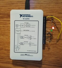
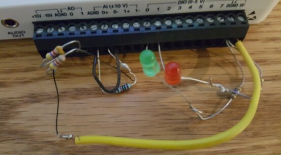
Using a myDaq:
The myDaq device has the following specifications:
| Digital outputs |
4.0mA at 3.3V |
| Analog outputs |
2.0mA at -10 to +10V |
The digital outputs of this device will function just as the ones on the 6001 family of devices: the supplied resistors will allow for safe operation. The analog output, however, can only supply 2mA. To limit 10V to 2mA, one needs to use a 5kOhm resistor. In addition, at 5V this small amount of current will produce less heat than would be obtained from the devices above. Luckily the myDaq has an output limit of 10V, so the total power dissipated at 10V with 5kOhm is almost as much as for the USB-6008 circuit above. In addition, one could configuring both analog outputs to heat the thermistor, each with its own 5k resistor. In this case, one would need to place them in close proximity to each other. Also, be sure to use separate resistors, one for each output. If a single resistor is applied across both outputs to try to double the current available, it would inevitably result that the two outputs were not set to the same Voltage level and they could damage each other. If a second voltage output is added to the NIDaqDA Driver, you may want to navigate to the Modules\Control Tab configuration screen and add that new channel to the list of Controller channels in the upper left. This will allow you to operate the channel directly from the main control tab of MICAS-X.
Note that the myDaq device only supports Differential input, so you will need to reconfigure the NIDaqAD Driver as Differential, rather than Single Ended. In addition, the thermistor must be connected slightly differently. The end of the thermistor that is connected to the analog ground must also have a wire connecting that analog ground terminal to the negative input of the analog input channel, marked AI0-. A myDaq with the required wiring is shown below.